
Electrical
Approach
My Scrambler’s electrical system involved four primary systems:
Engine wiring: My engine wiring harness came pre-installed on the LQ4 engine that I purchased from BD Turnkey Engines. The owner, Brian Dacus, and his son, Gage, reconfigured the factory wiring harness from the donor vehicle — in my case, a 2005 H2 — and re-installed it on the engine.
Vehicle wiring: I initially planned to reuse my OEM wiring harness. I did a respectable job of removing it from my Jeep, meaning I preserved the full lengths of most wires and labeled them accordingly. However, as I began the re-install process, I realized that many of the wires were corroded and the bulkhead connections were dirtier than hell. So, I bit the bullet and bought a brand-new wiring harness, part #10150, from Painless Wiring.
Gauge wiring: When I bought the Jeep and got it to run in it’s original/OEM state, I quickly realized that none of the factory gauges worked. Not one. Although I didn’t spend much time troublehshooting each gauges, I probably could have gotten them to work. But I decided to not even bother because they were in equally poor aesthetic condition — I needed to replace them. So, I invested in brand-new, direct-fit CJ gauge from Speedhut.
Vehicle grounding: This was the simplest part of the electrical system. I used Painless Wiring’s universal body/engine ground strap kit, which ensures that “all electrical components and lamps get proper grounds by allowing direct paths to ground.”
I used aftermarket components for these three systems, and, as we’ll see, there were surprisingly few connection points among them. Installation was daunting at first, but things came together when I read the engine wiring harness and vehicle wiring harness installation manuals side by side — literally, side by side.
Engine wiring
BD Turnkey Engines reconfigures their wiring harnesses to meet the needs of your build. Seemingly across all their builds, though, you only need four wires connected “to actually start and run the engine.” These notes are from their wiring harness installation guide (which shows a few of my handwritten notes in the margins):
Battery (orange, 12V+): This is a positive, full-time, 12V+ source. It is separately fused. Avoid routing this connection through a “master” kill switch. The ECM goes through a learning process every time this connection is lost.
Ignition (red, 12V+): Generally from the crank/run side of keyed sources. It is separately fused.
Fuel pump (blue, 12V+): This is the 12V+ from the fuel pump relay. The relay is controlled by the ECM and is separately fused. When the ignition is turned on, the fuel pump will cycle approximately three seconds and turn off until cranking begins. Run directly to fuel pump.
Starter solenoid (purple, 12V+): This generally comes from the “crank” position of the key and what engages the starter to actually crank the engine over for starting. 12ga wire recommended.
Novak Conversions offers a comparable engine wiring harness modification solution. They, too, have four essential wires for constant battery, ignition/key-on, starter, and fuel pump.
Vehicle wiring
Since I used separate wiring for my engine and gauges, I only used the following components/sections of my aftermarket wiring harness from Painless Wiring:
Harness power
Front and rear lighting
Trailer hook-up
Under-hood, dash, and interior lighting
Radio
Cigarette lighter
Blower motor
Ignition wire
Starter wire
Horn
Brake, 4WD, and reverse warning/indicactors
Windshield wipers and fluid reservoir
Gauges
I used aftermarket gauges, all of which came with stand-alone wiring harnesses:
Tachometer
Speedometer
Coolant temperature
Fuel level
Volts
Oil pressure
Transmission temperature
Fuel pressure
Vehicle grounding
When it comes to grounding, I subscribe to the theory that “you can’t overdo it.” So, to properly ground my Scrambler, I ran grounding wires or straps between the following components:
Battery (negative side) to engine block
Engine block to frame
Body/firewall/bed to frame
Grill to frame
Fenders to frame
Dash to firewall
While not all of these grounds were strictly necessary today, in my view adding all of these grounding connections is a prudent step that helps future-proof the vehicle.
Connections among wiring harnesses
Engine wiring harness to vehicle wiring harness
My engine wiring harness only attached to the vehicle wiring harness at two points, the (1) ignition wire and the (2) starter solenoid wire:
The red ignition wire on my engine harness connected to the red/white wire, #920, on the vehicle wiring harness. See pages 93-95 of the Painless Wiring installation manual
The purple starter solenoid wire on my engine harness connected to the blue wire, #919, on the vehicle wiring harness. See pages 119-123 of the Painless Wiring installation manual
Engine wiring harness to gauges
My Jeep came with five factory gauges and a clock, and I added two more custom gauges. Here’s a breakdown of connection points from the engine harness to each of my gauges.
Tachometer
My modified engine wiring harness — sourced from a 2005 H2 — came with a black tachometer output signal wire that came from the ECM. I spliced this black wire into the yellow wire that came with my Speedhut tachometer.
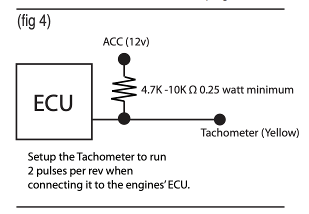
I also t-spliced a 4,700-10,000 ohm / 0.25 watt resistor into the tachometer connection to “boost” the ECM tach signal. (The engine wiring harness and the Speedhut gauge install kit both conveniently came with a resistor.) I then spliced the resistor wire into my cigarette lighter wire, which is an ACC/”keyed” 12V power source.
Here are resistor installation instructions from my engine builder, BD Turnkey Engines:
Some ECM’s tach signal is not strong enough for some aftermarket tachs. This method can be used to “boost” the signal from the ECM. All you do is hook up one end of a 680 ohm [0.25 watt] resistor (supplied below) to the tach wire, and [connect the other end of the resistor to a keyed 12V+. This may not be needed with all tachs and ECMs. The pre-2002 ECMs and tach combinations seem to be hit-and-miss. So far, all the 2003+ have had to have it.
The following diagram of how to install the resistor is from the Speedhut tachometer instructions.
Speedometer
No connection to engine harness. The Speedhut speedometer is GPS-enabled, which means it’s not tied into the engine, transmission, nor transfer case. It’s essentially self-contained.
Speedhut does have a wire available to installers who want to connect their new speedometer to a speed signal (other than the GPS). I opted not to make this connection, though I might revisit this decision.
Coolant temperature
No connection to engine harness. The Speedhut install kit came with a wire and temperature sensor, which I installed on an unused cylinder head port with this adapter. The extended length of the adapter is necessary to accomdate the full length of the temperature sensor!
Fuel level
No connection to engine harness. The Speedhut install kit came with a wire that connected to my aftermarket Novak Conversions in-tank fuel pump.
Volts
No connection to engine harness.
Oil pressure
No connection to engine harness. The Speedhut install kit came with a wire and pressure sensor, which I installed using this adapter.
Transmission temperature
No connection to engine harness. The Speedhut install kit came with a wire and temperature sensor, which I installed on my NV4500 using an aftermarket PTO cover like this one on eBay.
Fuel pressure
No connection to engine harness. The Speedhut install kit came with a wire and pressure sensor, which I tied into the fuel line using an AN fuel pressure adapter fitting.
Gauge wires to vehicle wiring harness
Keyed power (cigarette lighter wire)
All the gauges need keyed power, which I tied into the Painless Wiring cigarette lighter wire.
Of note, the Speedhut speedometer is GPS-enabled, which means it’ll lose satellite connectivity without power after four hours. The Speedhut speedometer installation instructions state:
GPS location is saved internally for up to a 4 hour period. After 4 hours it will take 30-40 seconds to acquire [a GPS] signal again.
Resources
Engine wiring
BD Turnkey Engines: Wiring harness installation instructions
LT1 Swap: Gen III GM Engine Wiring Harness Rework Procedures
Novak Conversions: The Novak Guide to GM Gen IIII+ Engine Conversion Wiring
Vehicle wiring
Painless Wiring: Wire Harness Installation Instructions Manual #90513, For Installing Part
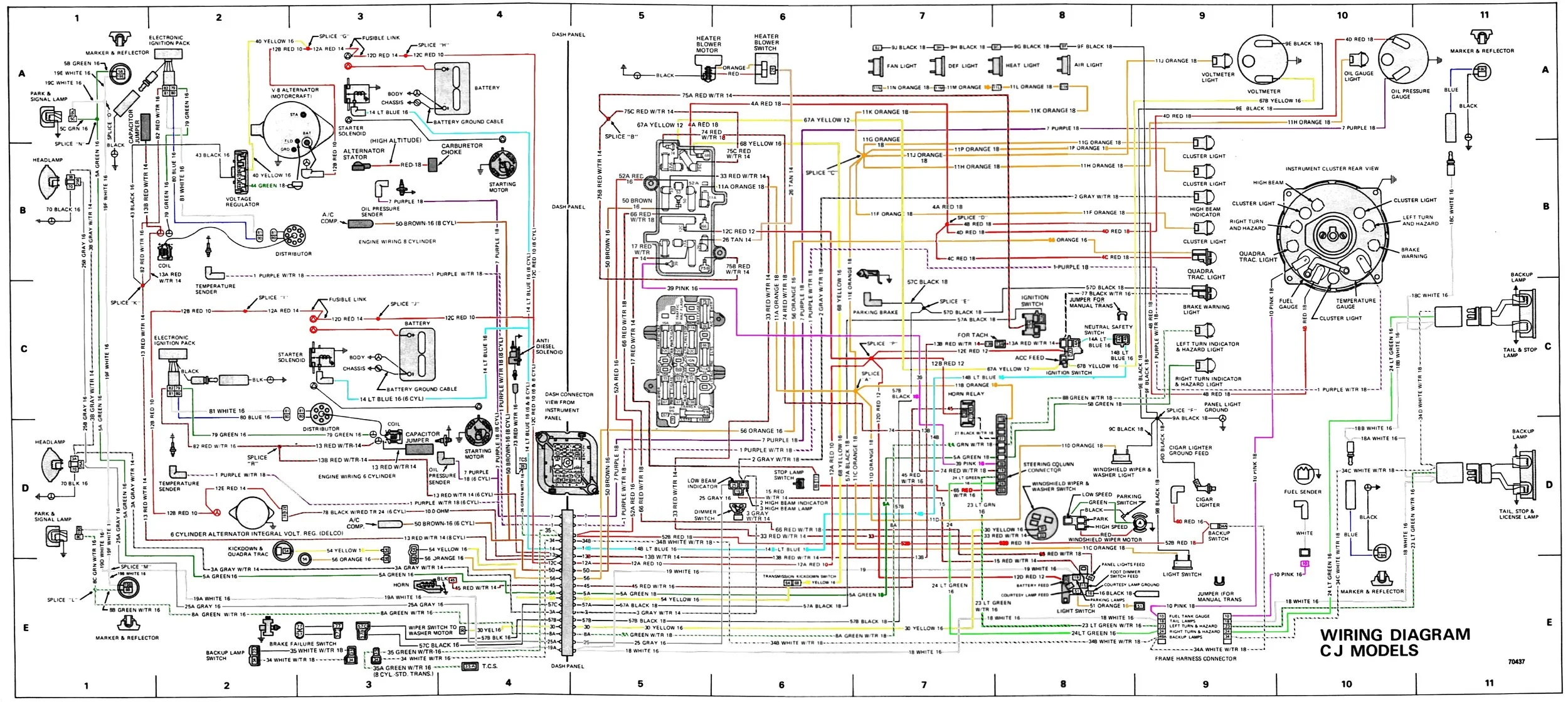
Jeep: Jeep CJ wiring diagram
Gauges wiring
Speedhut: Tachometer installation instructions
Speedhut: Speedometer, fuel level, and coolant temperature installation instructions
Speedhut: Voltage gauge installation instructions
Speedhut: Clock installation instructions
BD Turnkey Engines: Tachometer and resistor wiring instructions
Novak Conversions: Jeep CJ in-tank fuel pump installation requirements
Vehicle grounding
Painless Wiring: Universal body/engine ground strap kit instructions
Instructional videos
How to add a resistor to “boost” the ECM tachometer signal